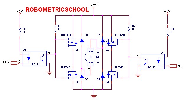
Your C2 & C3 ensure that this is/almost is long enough to destroy all mosfets. The crossover point of one mosfet switching off and the other switching on is not at the same voltage or you would like as safe and different.Īs the common gate voltage changes from high to low or low to high there is a large voltage range that BOTH Hi and Lo side mosfets will be ON. The inclusion of C2 & C3 slows down the switching time of your mosfets to the point of distruction. Your final circuit is "designed to FRY mosfets"

You have not learned anything from the replies suggessted. Otherwise you will be bungling around for year(s) just to get an H-Bridge to work. Check it out as it will greatly accelerate your learning and troubleshooting effort.
#H bridge mosfet driver board full#
The demo boards that have the Atmega88, you can connect an optical or Hall magnetic sensor servo to the demo board for full motor feedback and control.

One of their H-Bridge Demo Boards will be your benchmark system. I found a website that has a complete MOSFET H-Bridge HIP4081A Demo/Evaluation board system with 0.001 Ohm MOSFETs, H-bridge controller, with and without an Atmel AVR Atmega88 microcontroller, current sense amplifier, and all of the circuit protection components, as a Demo Board, at a great price. You can verify voltages and logic are correct on your system verses the benchmark system that already works with a known functional behavior. First you need a Benchmark system that you can learn and validate your generic system design to. You can also eliminate the Upper Diodes with this IC as well. It will provide MOSFET Gate Drive up to 2.5 amps peak drive current when only consuming 9ma total at 20KHz PWM. You will also need to use a PCB with at least 2oz copper traces to reduce trace resistance losses.īuild an H-Bridge using an Intersil HIP4081A. If you plan on powering your H-Bridge from a BATTERY, sourcing greater than 5 amps from the H-Bridge to the load, you will need to use low on resistance MOSFETS (less than 0.004 Ohms).

Diodes D1,D2, D3, D4 are clamping diodes to clamp negative (below ground) or positive source supply voltage clamps. :D First of all this is an OLD design from the stone age before there where MOSFET Gate Driver ICs.ġ.


 0 kommentar(er)
